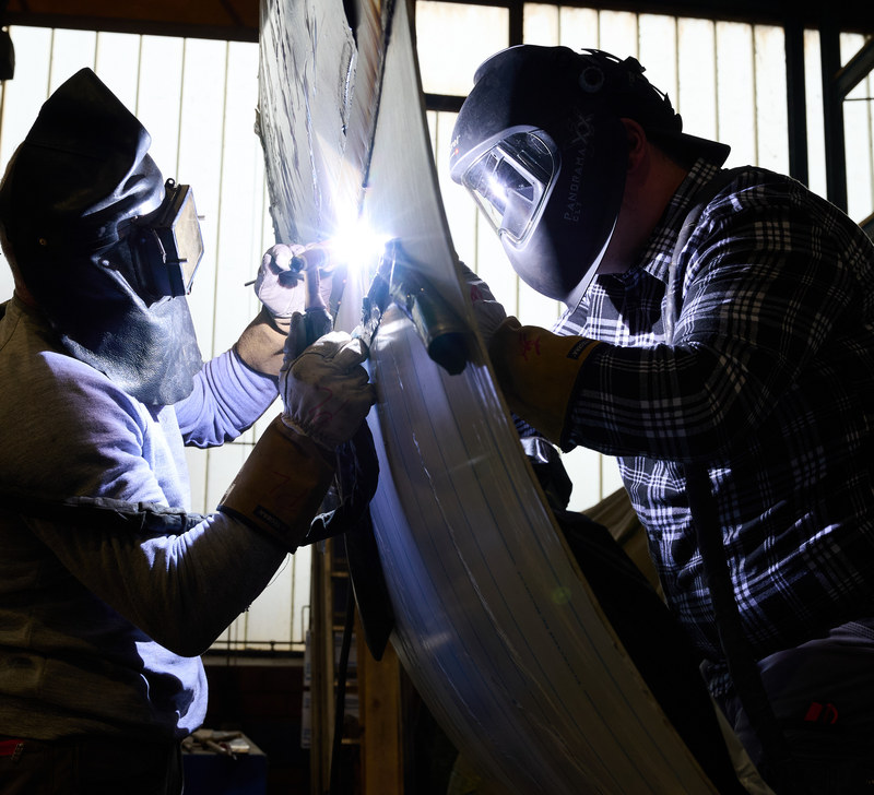
Two employees in welding helmets welding a metal component

Stainless steel weld fittings

Bends, tees and reducers for tank, plant and vessel construction.

Select design, series, size and material. Add drawings to your inquiry.

Two employees in welding helmets welding a metal component

Fittings for tank, plant and vessel construction

For tank, plant and vessel manufacturers, every fitting has to match the design. Purchasing and engineering need the same clear details for this: design, type of connection, tube dimension, material, surface finish and quantity.

The configurator helps you bring these details together. Add any further requirements and drawings to your inquiry. That way we can review the design you want and clarify open technical points with you.
Bends

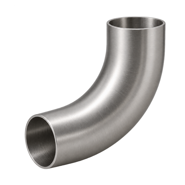
45 degree and 90 degree bends change the direction of your piping. In the configurator you select angle, dimension series and size to suit the design. Tube outside diameter, wall thickness, bending radius and connection dimensions describe the component required. For deviating geometries, please inquire with a drawing.
Reducers

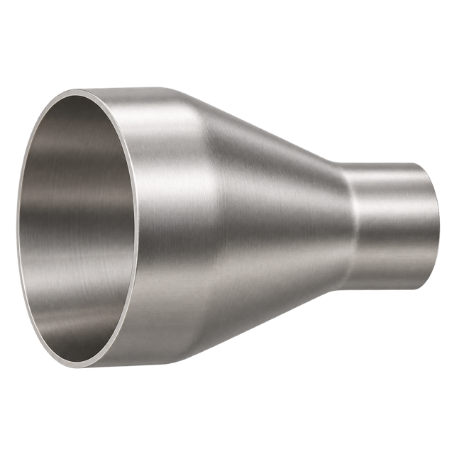
Reducers connect different tube sizes. Concentric and eccentric designs are available. The installation situation and your piping layout are decisive. State both connection sizes and the design you want so that the transition is clearly described.

Tees

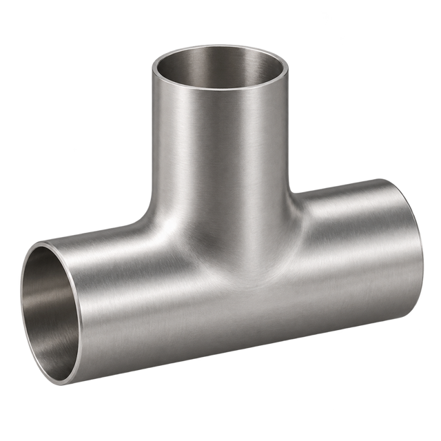
Tees split or join pipe runs. In equal tees the run and the branch have the same size; in a reducing tee the branch is smaller. Select run size, branch size and the matching dimension series. This makes the branch in your design unambiguous.

Custom fittings to drawing

Your geometry. Technically agreed.

If your requirement differs from the DIN 11865 range provided, send us a drawing or technical specification. Weiss Apparatebau manufactures components and assemblies to agreed requirements. We review feasibility, design and terms for your specific needs.

The following dimension tables help you select bends, tees and reducers in series A, B and C. The bend tables give tube outside diameter, wall thickness, bending radius and lengths for 45 and 90 degree designs. Check the dimensions together with your design; the size designation alone does not describe every connection.
Bends to DIN 11865 series A (metric, DN)
Size Tube OD Wall thickness Bending radius L1 L2 L3 at 45 degrees L3 at 90 degrees
DN06 8 1 20 45 33,3 25 25
DN08 10 1 25 50 35,4 25 25
DN10 13 1,5 26 51 35,8 25 25
DN15 19 1,5 35 60 39,5 25 25
DN20 23 1,5 40 65 41,6 25 25
DN25 29 1,5 50 90 60,7 40 40
DN32 35 1,5 55 95 62,8 40 40
DN40 41 1,5 60 100 64,9 40 40
DN50 53 1,5 70 110 69 40 40
DN65 70 2 80 120 73,1 40 40
DN80 85 2 90 145 92,3 55 55
DN100 104 2 100 155 96,4 55 55
DN125 129 2 187,5 270 160,2 82,5 82,5
DN150 154 2 225 325 193,2 100 100
DN200 204 2 300 400 224,3 100 100

All dimensions in millimetres. On narrow screens the table can be scrolled horizontally.

Bends to DIN 11865 series B (metric ISO, OD)
Size Tube OD Wall thickness Bending radius L1 L2 L3 at 45 degrees L3 at 90 degrees
NW10.2 10,2 1,6 20 45 33,3 25 25
NW13.5 13,5 1,6 20 45 33,3 25 25
NW17.2 17,2 1,6 28 53 36,6 25 25
NW21.3 21,3 1,6 30 55 37,4 25 25
NW26.9 26,9 1,6 28,5 68,5 51,8 40 40
NW33.7 33,7 2 38 78 55,7 40 40
NW42.4 42,4 2 47,5 87,5 59,7 40 40
NW48.3 48,3 2 57 97 63,6 40 40
NW60.3 60,3 2 76 116 71,5 40 40
NW76.1 76,1 2 95 150 94,4 55 55
NW88.9 88,9 2,3 114,5 169,5 102,4 55 55
NW114.3 114,3 2,3 152,5 207,5 118,2 55 55
NW139.7 139,7 2,6 190,5 245,5 133,9 55 55
NW168.3 168,3 2,6 228,5 283,5 149,7 55 55
NW219.1 219,1 2,6 305 385 206,3 80 80

All dimensions in millimetres. On narrow screens the table can be scrolled horizontally.

Bends to DIN 11865 series C (inch, OD)
Size Tube OD Wall thickness Bending radius L1 L2 L3 at 45 degrees L3 at 90 degrees
0.25 6,35 0,89 14,3 66,7 50,8 44,9 52,4
0.375 9,53 0,89 28,6 66,7 50,8 39 38,1
0.5 12,7 1,65 28,6 76,2 57,2 45,4 47,6
0.75 19,05 1,65 28,6 76,2 57,2 45,4 47,6
1 25,4 1,65 38,1 76,2 57,2 41,4 38,1
1.5 38,1 1,65 57,2 95,3 63,5 39,8 38,1
2 50,8 1,65 76,2 120,7 76,2 44,6 44,5
2.5 63,5 1,65 95,3 139,7 85,7 46,2 44,4
3 76,2 1,65 114,3 158,8 92,1 44,8 44,5
4 101,6 2,11 152,4 203,2 114,3 51,2 50,8
6 152,4 2,77 228,6 292,1 158,8 64,1 63,5

All dimensions in millimetres. On narrow screens the table can be scrolled horizontally.

Equal tees to DIN 11865, series A (metric DN)
Size L0 L L2 L1, branch offset
DN06 30 60 30 11
DN08 30 60 30 11
DN10 35 70 35 11
DN15 35 70 35 11 ± 0,50
DN20 40 80 40 13 ± 0,50
DN25 50 100 50 16 ± 0,75
DN32 55 110 55 19,5 ± 0,75
DN40 60 120 60 23 ± 1
DN50 80 160 80 30 ± 1
DN65 105 210 105 40 ± 1,50
DN80 130 260 130 47,5 ± 1,50
DN100 155 310 155 58 ± 1,50
DN125 187,5 375 187,5 74 ± 3
DN150 225 450 225 90 ± 3
DN200 300 600 300 115 ± 3

Dimensions in mm; size designations according to the series stated. Please inquire separately about designs not listed. L0, L, L2 and L1 refer to the dimensions in the corresponding component drawing. A dash at L1 means no offset, not zero.

Equal tees to DIN 11865, series B (ISO/OD NW)
Size L0 L L2 L1, branch offset
NW10.2 30 60 30 11
NW13.5 32 64 32 11
NW17.2 34 68 34 10,1 ± 0,5
NW21.3 36 72 36 12,2 ± 0,5
NW26.9 55 110 55 15 ± 0,5
NW33.7 60 120 60 18,4 ± 0,75
NW42.4 65 130 65 23,2 ± 0,75
NW48.3 65 130 65 26,7 ± 1
NW60.3 90 180 90 33,7 ± 1
NW76.1 110 220 110 43,1 ± 1,5
NW88.9 130 260 130 49,5 ± 1,5
NW114.3 160 320 160 63,2 ± 1,5
NW139.7 200 400 200 79,9 ± 3
NW168.3 250 500 250 97,2 ± 3
NW219.1 300 600 300 123,6 ± 4

Dimensions in mm; size designations according to the series stated. Please inquire separately about designs not listed. L0, L, L2 and L1 refer to the dimensions in the corresponding component drawing. A dash at L1 means no offset, not zero.

Equal tees to DIN 11865, series C (inch)
Size L0 L L2 L1, branch offset
0.25 44,5 89 44,5 11
0.375 44,5 89 44,5 11
0.5 47,6 95,2 47,6 11
0.75 50,8 101,6 50,8 11 ± 0,5
1 54 108 54 14,2 ± 0,5
1.5 60,3 120,6 60,3 21,1 ± 0,75
2 73 146 73 28,9 ± 1
2.5 79,4 158,8 79,4 35,3 ± 1
3 85,7 171,4 85,7 43,1 ± 1,5
4 104,8 209,6 104,8 56,8 ± 1,5
6 142,9 285,8 142,9 90,1 ± 3

Dimensions in mm; size designations according to the series stated. Please inquire separately about designs not listed. L0, L, L2 and L1 refer to the dimensions in the corresponding component drawing. A dash at L1 means no offset, not zero.

Reducing tees to DIN 11865, series A
Run Branch L0 L L2 L1, branch offset
DN08 DN06 30 60 30 11
DN10 DN06 30 60 30 11
DN10 DN08 30 60 30 11
DN15 DN08 35 70 35 11 ± 0,50
DN15 DN10 35 70 35 11 ± 0,50
DN20 DN10 40 80 40 13 ± 0,50
DN20 DN15 40 80 40 13 ± 0,50
DN25 DN15 50 100 50 16 ± 0,75
DN25 DN20 50 100 50 16 ± 0,75
DN32 DN15 55 110 55 19 ± 0,75
DN32 DN20 55 110 55 19 ± 0,75
DN32 DN25 55 110 55 19 ± 0,75
DN40 DN20 60 120 60 22 ± 0,75
DN40 DN25 60 120 60 22 ± 0,75
DN40 DN32 60 120 60 22,5 ± 0,75
DN50 DN25 80 160 80 28 ± 0,75
DN50 DN32 80 160 80 28,5 ± 0,75
DN50 DN40 80 160 80 29 ± 1
DN65 DN32 105 210 80 37 ± 0,75
DN65 DN40 105 210 80 37,5 ± 1
DN65 DN50 105 210 80 38,5 ± 1
DN80 DN40 130 260 105 45 ± 1
DN80 DN50 130 260 105 46 ± 1
DN80 DN65 130 260 105 47,5 ± 1,50
DN100 DN50 155 310 130 55,5 ± 1
DN100 DN65 155 310 130 57 ± 1,50
DN100 DN80 155 310 130 57 ± 1,50
DN125 DN65 187,5 375 155 69,5 ± 1,50
DN125 DN80 187,5 375 155 69,5 ± 1,50
DN125 DN100 187,5 375 155 70,5 ± 1,50
DN150 DN80 225 450 187,5 82 ± 1,50
DN150 DN100 225 450 187,5 83 ± 1,50
DN150 DN125 225 450 187,5 86,5 ± 3
DN200 DN100 300 600 225 108 ± 1,50
DN200 DN125 300 600 225 111,5 ± 3
DN200 DN150 300 600 225 115 ± 3

Dimensions in mm; size designations according to the series stated. Please inquire separately about designs not listed. L0, L, L2 and L1 refer to the dimensions in the corresponding component drawing. A dash at L1 means no offset, not zero.

Reducing tees to DIN 11865, series B
Run Branch L0 L L2 L1, branch offset
NW13.5 NW10.2 32 64 32 11
NW17.2 NW10.2 34 68 34 10,1 ± 0,5
NW17.2 NW13.5 34 68 34 10,1 ± 0,5
NW21.3 NW10.2 36 72 36 12,2 ± 0,5
NW21.3 NW13.5 36 72 36 12,2 ± 0,5
NW21.3 NW17.2 36 72 36 12,2 ± 0,5
NW26.9 NW13.5 55 110 55 15 ± 0,5
NW26.9 NW17.2 55 110 55 15 ± 0,5
NW26.9 NW21.3 55 110 55 15 ± 0,5
NW33.7 NW17.2 60 120 60 18,4 ± 0,5
NW33.7 NW21.3 60 120 60 18,4 ± 0,5
NW33.7 NW26.9 60 120 60 18,4 ± 0,5
NW42.4 NW21.3 65 130 65 22,7 ± 0,5
NW42.4 NW26.9 65 130 65 22,7 ± 0,5
NW42.4 NW33.7 65 130 65 22,7 ± 0,75
NW48.3 NW26.9 65 130 65 25,7 ± 0,5
NW48.3 NW33.7 65 130 65 25,7 ± 0,75
NW48.3 NW42.4 65 130 65 26,2 ± 0,75
NW60.3 NW33.7 90 180 90 31,7 ± 0,75
NW60.3 NW42.4 90 180 90 32,2 ± 0,75
NW60.3 NW48.3 90 180 90 32,7 ± 1
NW76.1 NW42.4 110 220 90 40,1 ± 0,75
NW76.1 NW48.3 110 220 90 40,6 ± 1
NW76.1 NW60.3 110 220 90 41,6 ± 1
NW88.9 NW48.3 130 260 110 47 ± 1
NW88.9 NW60.3 130 260 110 48 ± 1
NW88.9 NW76.1 130 260 110 49,5 ± 1,5
NW114.3 NW60.3 160 320 130 60,7 ± 1
NW114.3 NW76.1 160 320 130 62,2 ± 1,5
NW114.3 NW88.9 160 320 130 62,2 ± 1,5
NW139.7 NW76.1 200 400 160 74,9 ± 1,5
NW139.7 NW88.9 200 400 160 74,9 ± 1,5
NW139.7 NW114.3 200 400 160 75,9 ± 1,5
NW168.3 NW88.9 250 500 200 89,2 ± 1,5
NW168.3 NW114.3 250 500 200 90,2 ± 1,5
NW168.3 NW139.7 250 500 200 94,2 ± 3
NW219.1 NW114.3 300 600 250 115,6 ± 1,5
NW219.1 NW139.7 300 600 250 119,6 ± 3
NW219.1 NW168.3 300 600 250 122,6 ± 3

Dimensions in mm; size designations according to the series stated. Please inquire separately about designs not listed. L0, L, L2 and L1 refer to the dimensions in the corresponding component drawing. A dash at L1 means no offset, not zero.

Reducing tees to DIN 11865, series C
Run Branch L0 L L2 L1, branch offset
0.375 0.25 44,5 89 44,5 11
0.5 0.25 47,6 95,2 47,6 11
0.5 0.375 47,6 95,2 47,6 11
0.75 0.375 50,8 101,6 50,8 11 ± 0,5
0.75 0.5 50,8 101,6 50,8 11 ± 0,5
1 0.5 54 108 54 14,2 ± 0,5
1 0.75 54 108 54 14,2 ± 0,5
1.5 0.75 60,3 120,6 60,3 20,6 ± 0,5
1.5 1 60,3 120,6 60,3 20,6 ± 0,5
2 1 73 146 66,7 26,9 ± 0,5
2 1.5 73 146 66,7 27,4 ± 0,75
2.5 1.5 79,4 158,8 73 33,8 ± 0,75
2.5 2 79,4 158,8 73 35,3 ± 1
3 1.5 85,7 171,4 79,4 40,1 ± 0,75
3 2 85,7 171,4 79,4 41,6 ± 1
3 2.5 85,7 171,4 79,4 41,6 ± 1
4 2 104,8 209,6 98,4 54,3 ± 1
4 2.5 104,8 209,6 98,4 54,3 ± 1
4 3 104,8 209,6 98,4 55,8 ± 1,5
6 3 142,9 285,8 123,8 83,1 ± 1,5
6 4 142,9 285,8 130,2 83,1 ± 1,5

Dimensions in mm; size designations according to the series stated. Please inquire separately about designs not listed. L0, L, L2 and L1 refer to the dimensions in the corresponding component drawing. A dash at L1 means no offset, not zero.

Reducers to DIN 11865, series A (metric DN)
from to L
DN08 DN06 38
DN10 DN06 38
DN10 DN08 38
DN15 DN08 60
DN15 DN10 60
DN20 DN10 60
DN20 DN15 60
DN25 DN15 70
DN25 DN20 70
DN32 DN20 80
DN32 DN25 80
DN40 DN20 90
DN40 DN25 90
DN40 DN32 90
DN50 DN25 90
DN50 DN32 90
DN50 DN40 90
DN65 DN40 110
DN65 DN50 110
DN80 DN50 110
DN80 DN65 110
DN100 DN65 135
DN100 DN80 135
DN125 DN80 150
DN125 DN100 150
DN150 DN100 170
DN150 DN125 170
DN200 DN125 230
DN200 DN150 230

Dimensions in mm; size designations according to the series stated. Please inquire separately about designs not listed.

Reducers to DIN 11865, series B (ISO/OD NW)
from to L
NW13.5 NW10.2 38
NW17.2 NW10.2 60
NW17.2 NW13.5 60
NW21.3 NW13.5 60
NW21.3 NW17.2 60
NW26.9 NW17.2 60
NW26.9 NW21.3 60
NW33.7 NW21.3 70
NW33.7 NW26.9 70
NW42.4 NW26.9 80
NW42.4 NW33.7 80
NW48.3 NW26.9 90
NW48.3 NW33.7 90
NW48.3 NW42.4 90
NW60.3 NW33.7 100
NW60.3 NW42.4 100
NW60.3 NW48.3 100
NW76.1 NW48.3 110
NW76.1 NW60.3 110
NW88.9 NW60.3 110
NW88.9 NW76.1 110
NW114.3 NW76.1 135
NW114.3 NW88.9 135
NW139.7 NW88.9 150
NW139.7 NW114.3 150
NW168.3 NW114.3 170
NW168.3 NW139.7 170
NW219.1 NW139.7 230
NW219.1 NW168.3 230

Dimensions in mm; size designations according to the series stated. Please inquire separately about designs not listed.

Reducers to DIN 11865, series C (inch)
from to L
0.375 0.25 41,28
0.5 0.25 47,63
0.5 0.375 47,63
0.75 0.375 50,8
0.75 0.5 53,98
1 0.5 63,5
1 0.75 53,98
1.5 0.75 76,2
1.5 1 63,5
2 1 85,73
2 1.5 63,5
2.5 1.5 85,73
2.5 2 63,5
3 1.5 107,95
3 2 85,73
3 2.5 66,68
4 2 130,18
4 2.5 107,95
4 3 98,43
6 3 184,15
6 4 142,88

Dimensions in mm; size designations according to the series stated. Please inquire separately about designs not listed.

Your fitting, clearly specified

Send us design, dimensions, material, surface finish and quantity. Drawings and the certificates you need complete the technical clarification.

Series A, B or C: which dimensions fit?

The dimension series has to match the existing piping. Series A is metric by nominal size (DN), series B metric by tube outside diameter of the ISO series, series C in inches by tube outside diameter.

Check tube outside diameter and wall thickness. A similar nominal size does not make the series interchangeable.

If the assignment is unclear, add the actual dimensions and your specification to the technical inquiry.

Weld fittings to DIN 11865

Selecting design and connection
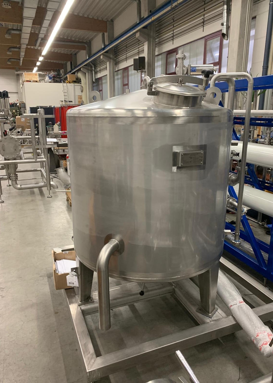
Vessel and connected piping of a water treatment plant

The Weiss configurator offers separate selection paths for 45 and 90 degree bends, equal and reducing tees as well as concentric and eccentric reducers.

In addition to the standard, the dimension series, size and specific geometry are required. Metric, ISO and inch data must not be treated as equivalent just because the nominal size is similar. Check the actual tube and connection dimensions.

Weld ends are permanently integrated into the piping. Tri-Clamp connections belong to detachable connection technology. Please state the type of connection you need explicitly. Include any special standards or deviating specifications in full in your inquiry so that we can review them separately.

For these designs

  • Tank and vessel construction

  • Plant and system construction

  • Process equipment and mechanical engineering

  • Industrial piping

  • Stainless steel assemblies to drawing

  • Technical clarification for your field of use

Stainless steel for your requirements

The fittings configurator offers the stainless steel materials 1.4404 and 1.4435. The requirements of your plant are decisive: medium, cleaning, temperature and the certificates intended.

Please state the material number you need as clearly as possible. We review further materials and special designs on the basis of your drawing or specification.
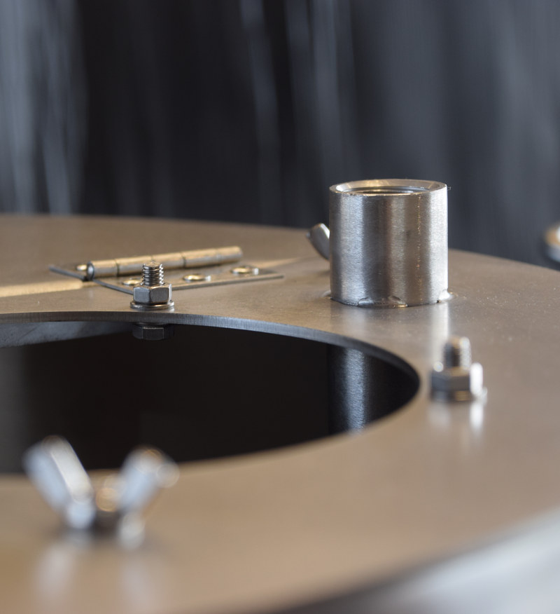
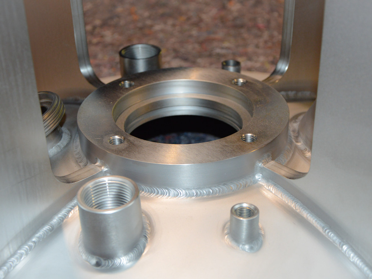
Detail of a stainless steel vessel lid with opening and connection ferrule

In-house production for your custom parts

Weld fittings and related stainless steel assemblies may require additional machining steps. Weiss Apparatebau combines welding and machining under one roof. Which processes suit your component is clarified from the drawing and the agreed requirements.
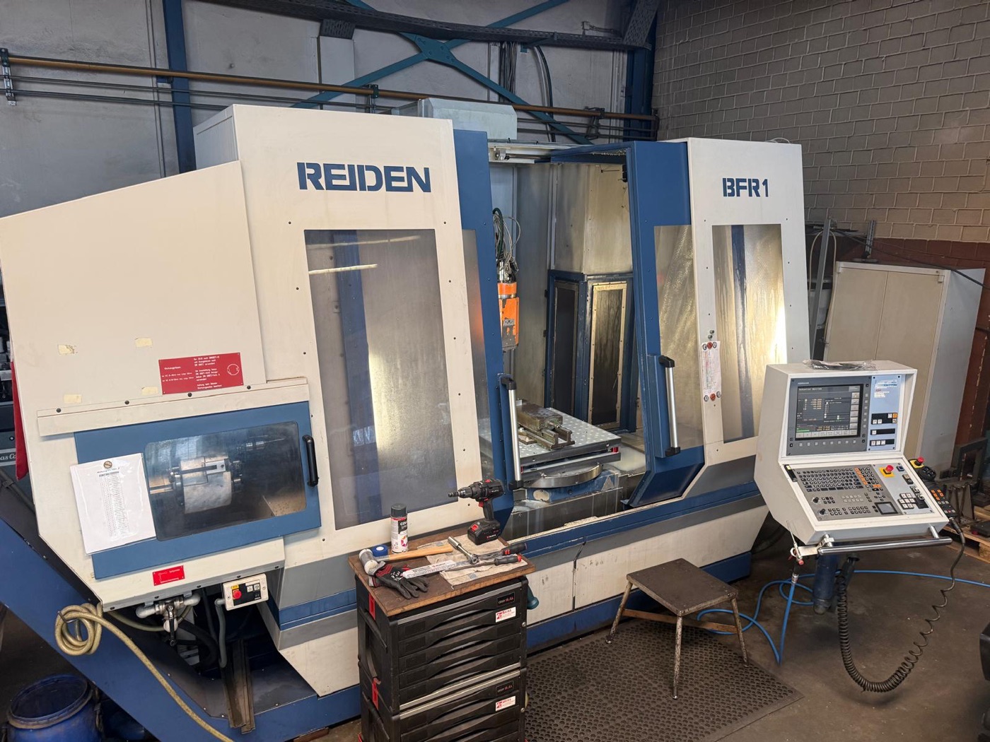
CNC milling for stainless steel components
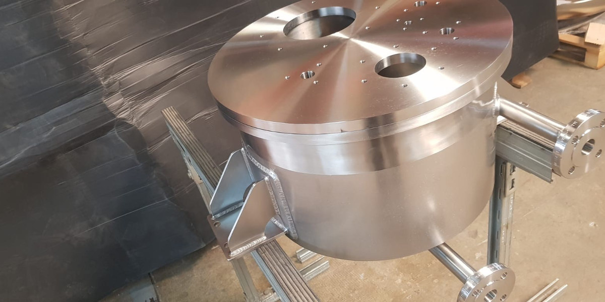
  • CNC machining for components and assemblies to drawing.

  • Machined faces and connection geometries are agreed on the basis of your technical requirements.

  • For custom parts, tolerances, datum edges and the later installed position count as much as the outside dimensions. Complete drawings help to clarify these requirements before production.

Metal reactor component with machined cover plate and bracket

Jigs and custom components

  • Machining for jigs, tooling and custom stainless steel components.

  • Machining is matched to geometry, material and intended use.

  • Whether a single part or a repeat design: tell us the quantity you need and send the documents you have. That lets us review the scope of production and the machining steps required.

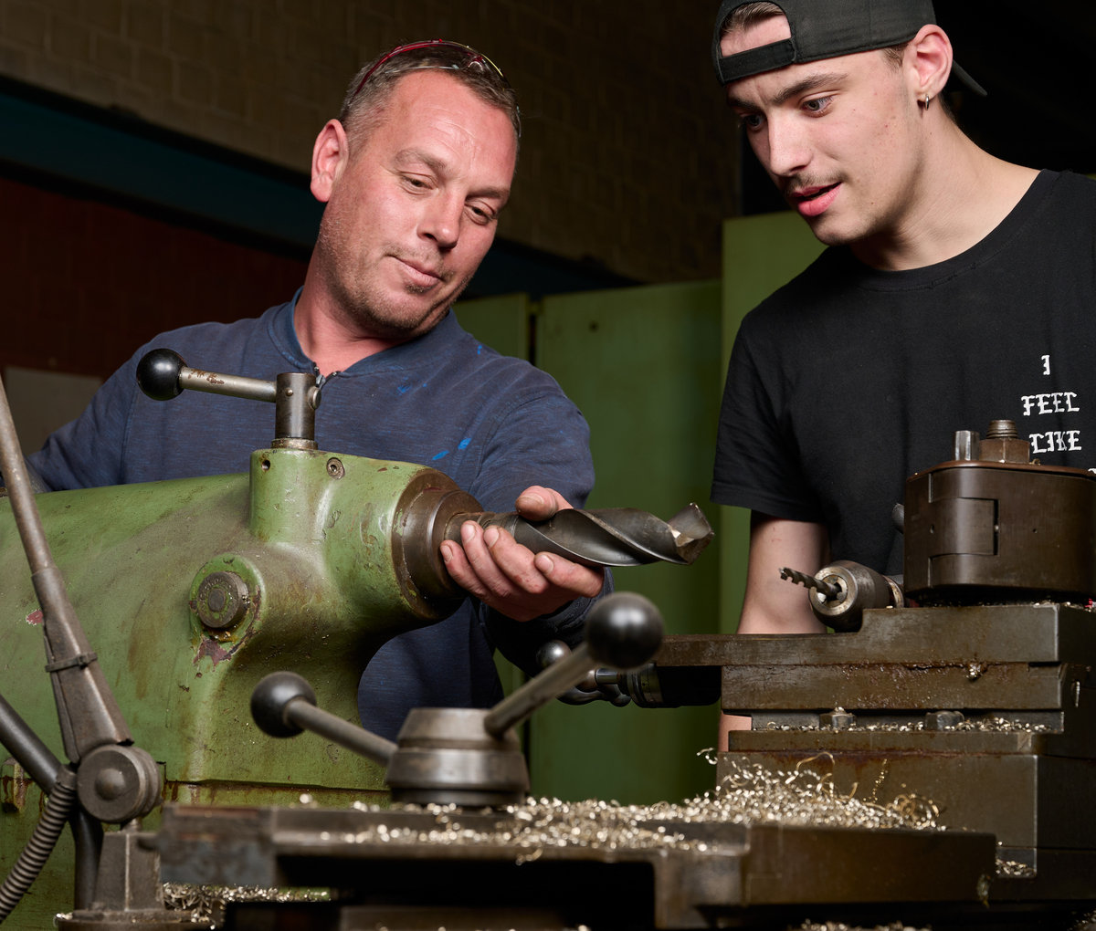
Two employees at a lathe with a clamped workpiece

Turning of stainless steel components
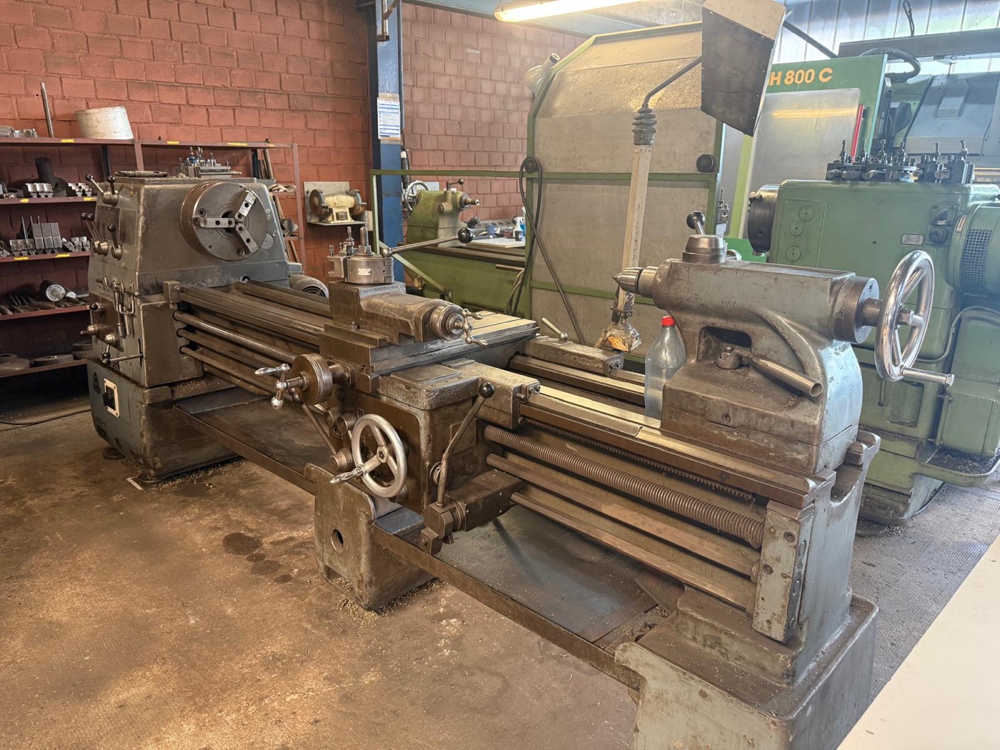
  • Turning complements the production of stainless steel parts and assemblies.

  • Diameters, lengths, connection dimensions and tolerances belong in your specification. Additional machining and special geometries are agreed project by project.

Clarifying special dimensions

  • Drawing, material, surface finish and quantity form the basis of your inquiry.

  • A selection in the configurator does not replace the clarification of a custom-made part. For deviating dimensions or special installation conditions we review the technical implementation on the basis of your documents.

Insights into stainless steel production

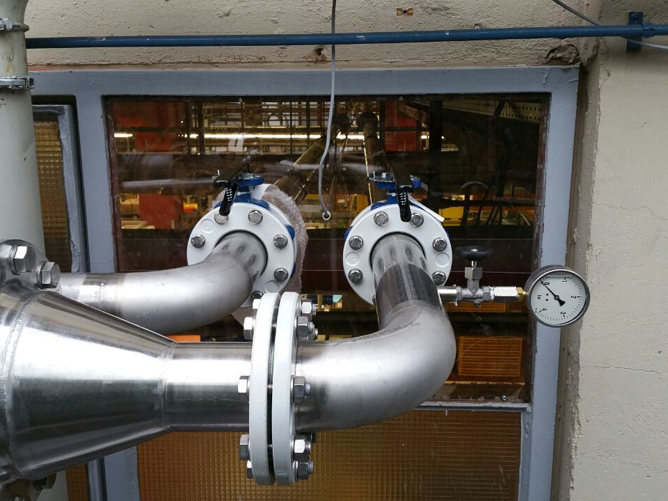
The images show work already completed in production at Weiss Apparatebau. They give an insight into how we machine stainless steel components and assemblies. The design of your fitting is agreed on the basis of your requirements.
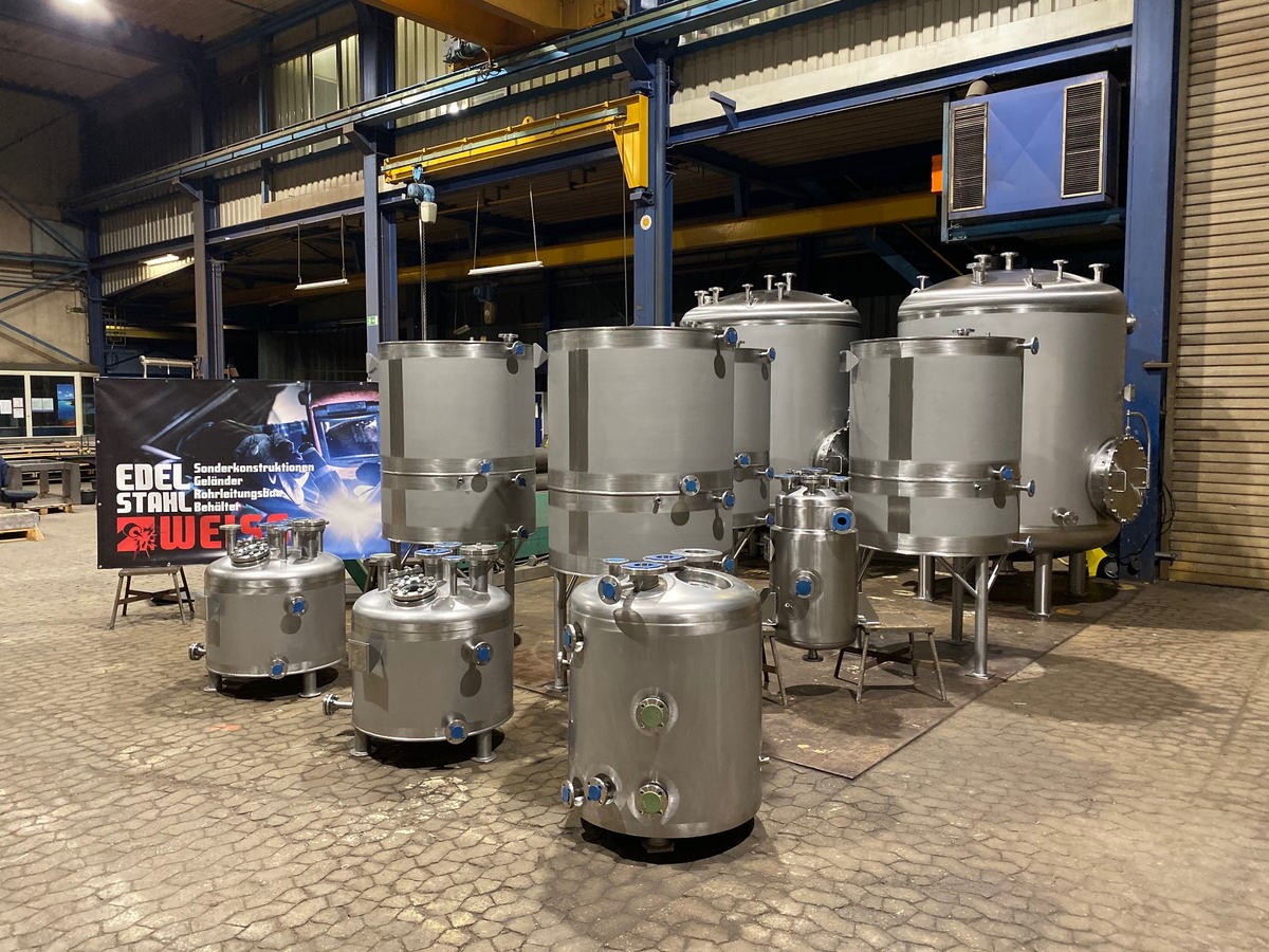
Several stainless steel vessels of different sizes in the Weiss Apparatebau workshop
Stainless steel piping with bend, flange connections and reducer
Close-up of weld seams on pipe ferrules and a flange connection
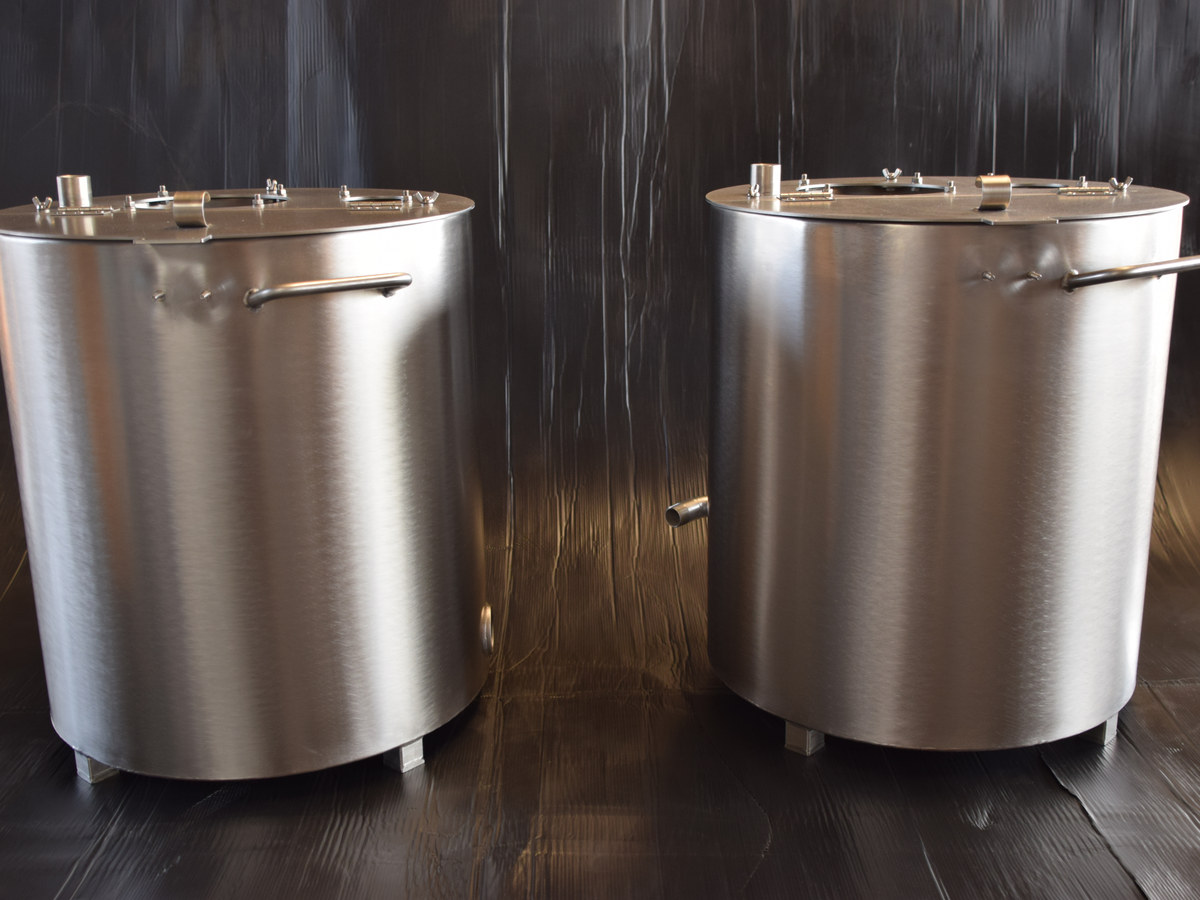
Two stainless steel vessels with closed lids and side connections
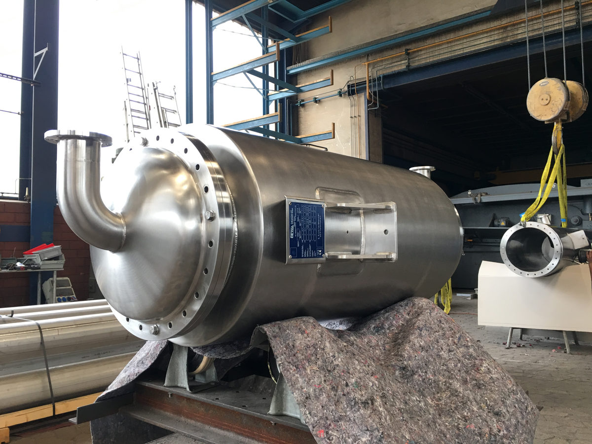
Horizontal vessel with a large flange connection and bent piping
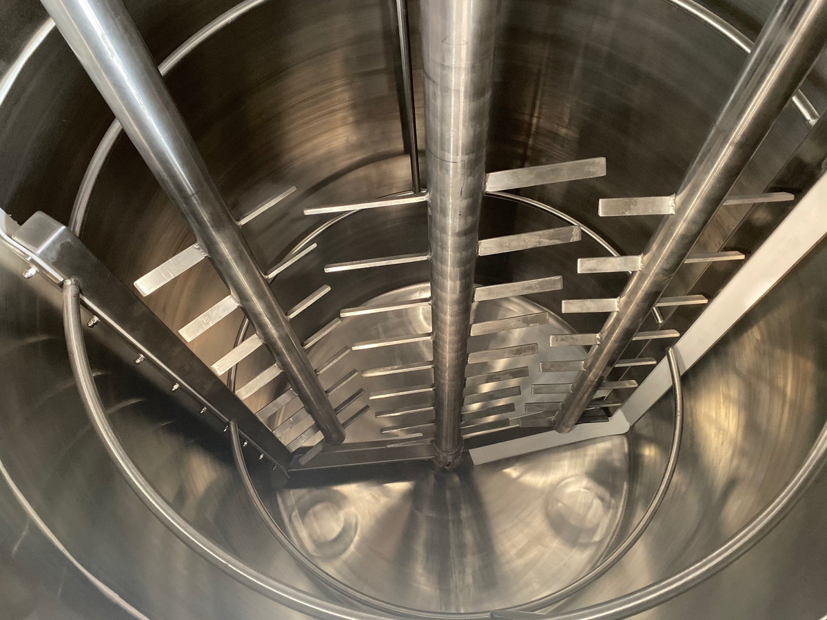
Interior view of a dough mixing vessel with internals
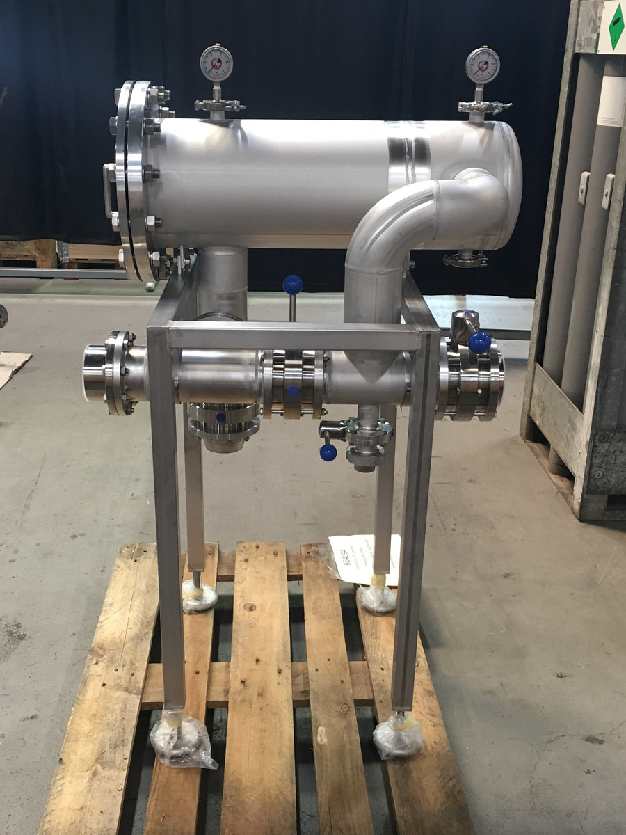
Process unit on a frame with pipe connections and pressure gauges

From component to assembly

Combining welding and machining

Do you need more than a single fitting? We also agree components and assemblies to drawing or technical specification with you. In-house welding and machining allow connected production sequences. Scope and certificates are agreed for each project.
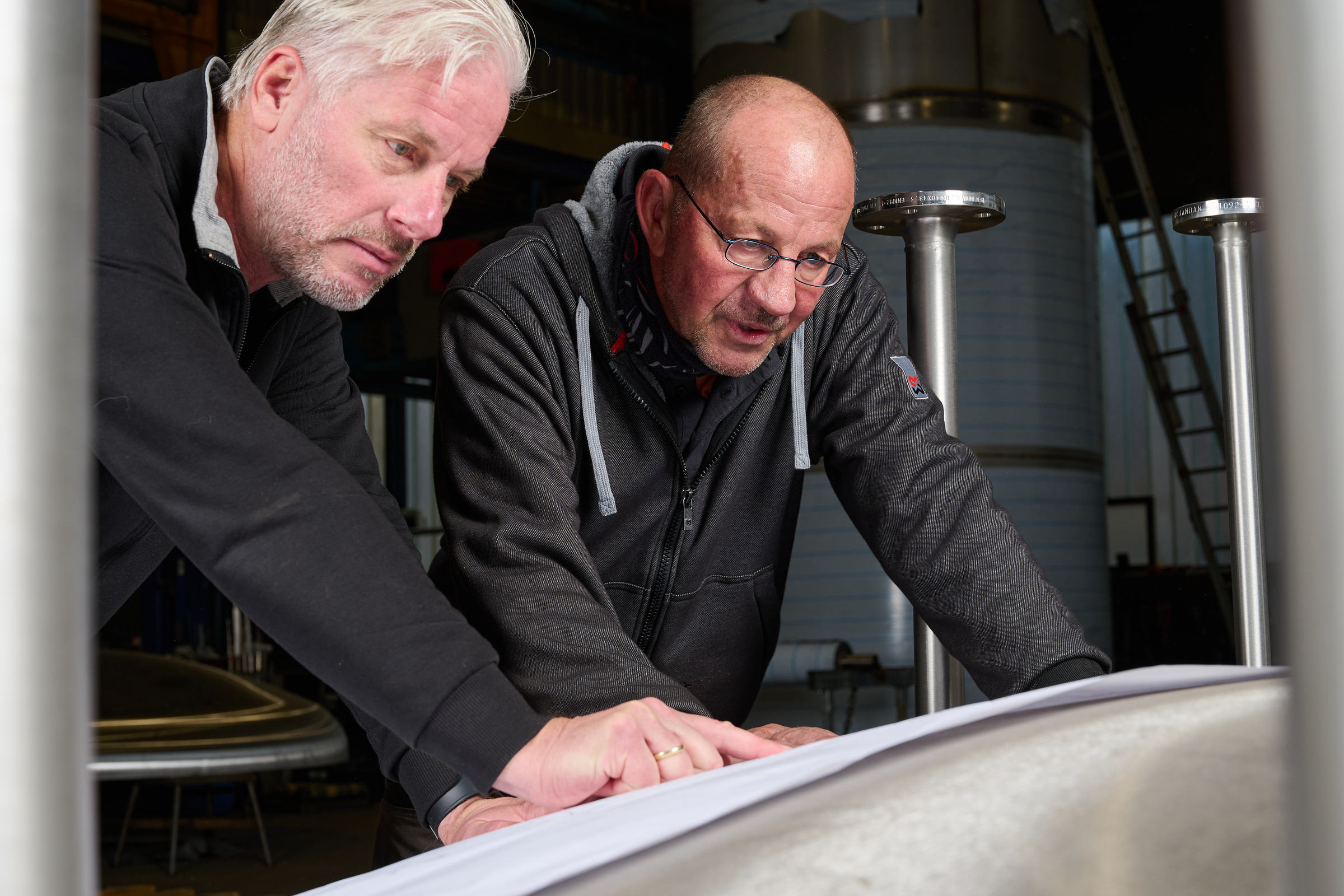
Two employees discussing a technical drawing in production

How to inquire about your weld fittings

Select. Complete. Clarify technically.

01. Select design and dimensions

Start with a bend, tee or reducer. Select the dimension series and size to match your piping. For reducing components both connection sizes are required. Note any deviating dimensions and special installation conditions.

02. Define the design

Add material, surface finish and quantity. The configurator offers 1.4404 and 1.4435 together with the surface finishes provided for each. The inspection and material certificates you want should already be part of your inquiry.

03. Send your documents

Transfer the configuration into your inquiry and add drawings or technical specifications. Describe special dimensions and additional requirements explicitly. That way purchasing and engineering work from the same details.

04. Confirm the design

We review the combination requested and clarify open technical points with you. The specific design, availability, documentation and terms are then confirmed for your requirements.
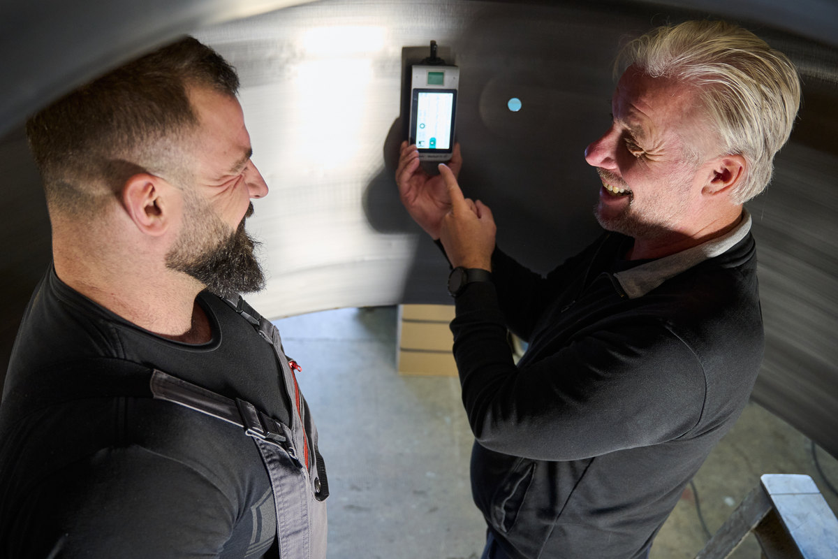
Two employees applying a measuring device to the wall of a vessel

Keeping surface finishes and certificates in mind

The surface finish has to suit the component and the requirements of your plant. The configurator distinguishes between mechanically polished and electropolished designs among others. Pickling, passivating or grinding may be added depending on component and order.

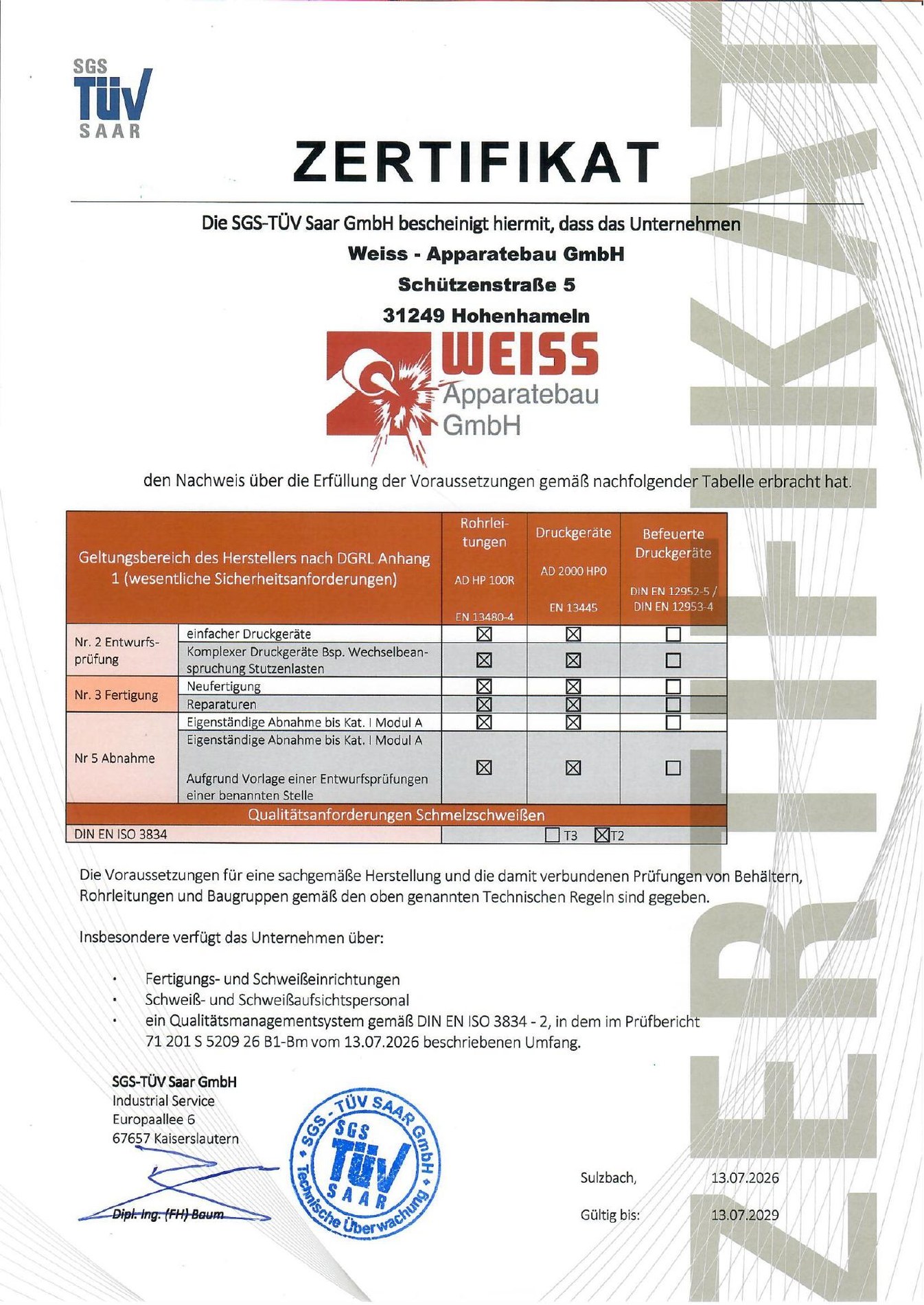
Please state required roughness values, inspection certificates and material certificates in your inquiry if possible. The certificate held by Weiss Apparatebau for AD 2000 HP0 and DIN EN ISO 3834-2 refers to the stated scope of fabrication. It does not replace the certificates agreed for your specific component.

DIN 11865

Selection basis for weld fittings

1.4404

Stainless steel material in the configurator

1.4435

Further material choice in the configurator

OEM

For tank, plant and vessel manufacturers

Frequently asked questions about weld fittings

Designs, materials, special dimensions and inquiries: answers for purchasing and engineering.

The DIN 11865 range covers 45 and 90 degree bends, equal and reducing tees as well as concentric and eccentric reducers. Select the design you need and add dimension, material, surface finish and quantity. Availability is confirmed after we have reviewed your inquiry.

State design, type of connection, dimension series, size, material, surface finish and quantity. For reducers and reducing tees both connection sizes are required. Add drawings, special dimensions and the inspection or material certificates you want.

You can inquire about deviating dimensions, single parts and custom designs with a drawing or technical specification. We review feasibility, design and terms for your requirements. This does not imply a blanket delivery commitment for every special dimension.

The fittings shown in the configurator are offered in 1.4404 and 1.4435. Further materials are reviewed on request. Please state the material number required and the operating requirements as precisely as possible.

The surface finishes provided in the configurator differ by component and design. H4 denotes a mechanically polished surface, H4o an electropolished one. If your specification requires a particular roughness value, state it in your inquiry and have the assignment to the component confirmed.

Inspection certificates, material documentation and further certificates are agreed to match the agreed scope. State your requirements before placing the order. Certification of the manufacturing operation does not automatically mean that every fitting is supplied with every certificate.

Series A is metric by nominal size, series B metric by tube outside diameter in the ISO series, series C in inches by tube outside diameter. Similar nominal sizes do not mean identical dimensions. For a clear assignment, please also state tube outside diameter and wall thickness.

Weld ends are permanently integrated into the piping. Tri-Clamp connections are detachable. Please state explicitly in your inquiry which type of connection you need.

Your technical inquiry

Request access to prices

Prices in the configurator are kept in a protected area. Tell us briefly who you are and you will receive your password by e-mail.

You are enquiring as